Mechanical timer consists of only clockwork or other mechanical movement for timing. This system is rarely used nowadays.
An Electromechanical timer consists of a motor and a gear system, whose slow rotation will mechanically control the switch. Electronic Timers are the most commonly used timers in various applications. Electronic timers consists of only semiconductor components along with switching devices. There are no moving parts in electronic timers and hence the life time will be more when compared to other timer systems. One of the best examples of a timer switch is the sleep mode in televisions and computers. If no key is pressed for a particular duration, the television or computer will automatically go to sleep mode where the device enters a low power consumption mode or may even be switched off. In this project, a simple timer switch for light is designed that will turn on a high power LED for a particular duration.
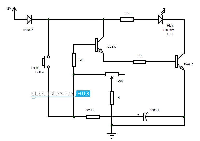
Circuit Diagram
Components Required
BC547 — 1 BC337 — 1 1N4007 — 1 1000µF — 1 High Intensity LED — 1 100 KΩ POT — 1 12 KΩ — 1 10 KΩ — 1 1 KΩ — 1 270Ω — 1 220Ω — 1 Switch — 1
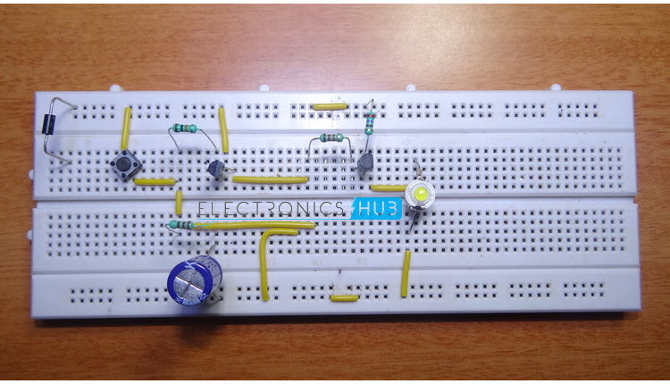
Circuit Design of Timer Switch for Light
The design of the timer switch is very simple. A diode is connected from the supply to safeguard the circuit from accidental reverse polarity connection and also to restrict any flow in to the source which is the car battery. A switch or push button is used to trigger the light. Two transistors are used to control the circuit: BC547 and BC337. The output of the BC547 transistor will drive the BC337 transistor. The emitter of BC547 is connected to base of BC337 via 12K resistor. A high intensity LED along with a series current limiting resistor are connected between supply and collector of BC337. The emitter of BC337 is connected to ground. A 10K resistor in series with 100K POT are used at the input of the BC547, with 10K resistor connected to base of BC547 and wiper of variable resistor connected to ground. The supply is given at the junction of these resistors. A 1000µF capacitor in series with 220Ω resistor is connected between junction and ground.
Working of Timer Switch
A transistor based electronic timer is designed here. The timer is based on the charging and discharging of the capacitor in the RC network. The design of the circuit is simple and the working is explained here. When the switch is closed, the transistor BC547 is turned on. The 1000µF capacitor will charge at the same time through 220Ω resistor. As BC547 is turned on and its emitter is connected to the base of BC337 through 12K resistor, it will trigger BC337 and it starts conducting. As the LED is connected to collector of BC337, it is turned on. 270Ω resistor acts as the current limiting resistor for the LED. When the switch is opened or button is released, BC547 will stay turned on due to the charge from the capacitor. The time of discharge of capacitor through 10KΩ resistor and 100KΩ POT can be set by adjusting the variable resistor. A 1KΩ resistor is connected between the wiper of the variable resistor and ground. This resistor acts as a protection resistor when the resistance of variable resistor is completely reduced to 0Ω approximately and there will be no short between supply and ground through variable resistor. The timer switch in this project will keep the LED turned on for a maximum of approximately 2 minutes. NOTE
A simple timer light switch is designed in this project. The light will stay on for a particular duration and is automatically turned off after preset time. The time duration can be set by varying the variable resistor and changing the value of capacitor.
Comment * Name * Email * Website
Δ
![]()
![]()
![]()
![]()
![]()

