So, in this guide, let us take a closer look at a typical automotive relay, the pinout and terminology associated with relays and also the relay wiring diagram.
What is a Relay?
As mentioned earlier, a relay is essentially a switch. Unlike a traditional switch, which we flip or toggle to make it ON and OFF, a relay is an electromechanical switch. The ‘mechanical’ action of moving the switch between ON and OFF positions is achieved by an ‘electrical’ signal. In its basic form, a relay consists of an electromagnet and an actuator. When a small control signal flows through the coil of electromagnet, it attracts the actuator. This action will make the actuator to move from one position/contact (this is often called normally close or NC contact) to another position/contact (which is often called normally open or NO contact). When we remove or disengage the control signal to the coil, it deactivates the electromagnet and the actuator return to its original position.
Where we use Relays?
The beauty of relays is that the parts that acts as switch in the relay (which consists of the actuator and the contacts) are isolated from the mechanism that activates or deactivates the switch (which is the coil and electromagnet). This construction is extremely useful if you want to control a large current switch with a tiny control signal from a microcontroller (or similar low voltage devices). This is exactly how we often use relays in real-life applications. Assume there is a microcontroller which is configured to control an AC mains powered appliance. Relays are very useful in such scenarios as the microcontroller can provide the control signal to the relay’s coil and the contacts switch ON or OFF the appliance. Another major application of relays is in automobiles. There are several high current/power components in a typical car (or any automobile for that matter) such as headlights, heater/cooling system, blower, motors, audio system, etc. We can place the relays close to the appliance and send a tiny control signal wire from the car’s computer to the relay. This saves a ton of copper wire as the control wire doesn’t carry high current and all the high current devices are in the close proximity to the relay.
Important Relay Terminology
As cars (or automobile in general) are a major application of relays, let us discuss some of the important terminology associated with relays. The following discussion is applicable to automotive relays but some parts of it can be applied to relays in general (such as the NO, NC contacts). A typical relay consists of 5 pins. They are:
Two Coil Pins COM Normally Open (NO) Normally Closed (NC)
We apply the control signal across the two coils pins. For a 12V relay, the potential of this control signal must be 12V. The remaining three i.e., COM, NO and NC are part of the high current switch. In that, the COM pin acts as one terminal of the switch. It also acts as the pivot of the actuator level. We usually connect the COM pin to the 12V supply that goes to the component such as light bulb. Coming to the other two pins, the Normally Closed (NC) pin, as the name suggests, is by default connected to the COM pin when there is no control signal on the coil. But as soon as we apply a valid control signal across the coil, the actuator moves to the Normally Open (NO) pin. Generally, the device that must be controlled by the relay is connected to the NO pin but this can change depending on the application. Coming to automotive relays, the following table describes the commonly used pin numbers.
Types of Automotive Relays
There are two types of commonly used automotive relays. They are:
4-Pin Relays
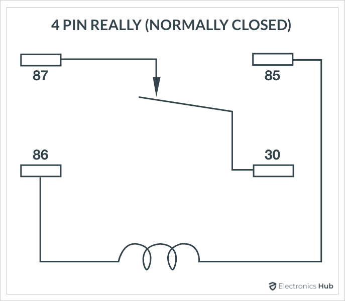
Normally Closed (NC) 4-Pin Relay.
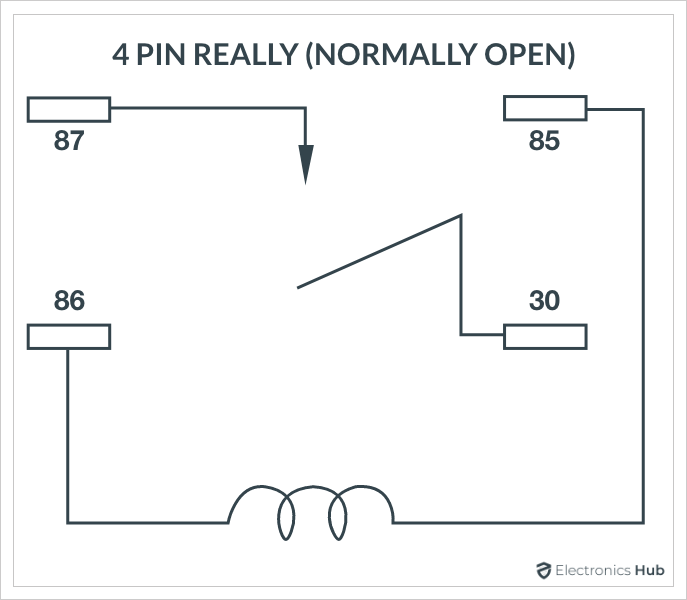
Normally Open (NO) 4-Pin Relay.
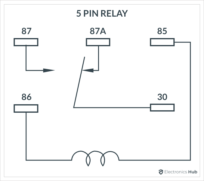
5-Pin Relays
Both these relays are very similar except that the 4-Pin relay doesn’t have the ‘87a’ or the Normally Closed (NC) pin whereas the 5-Pin relay has it.
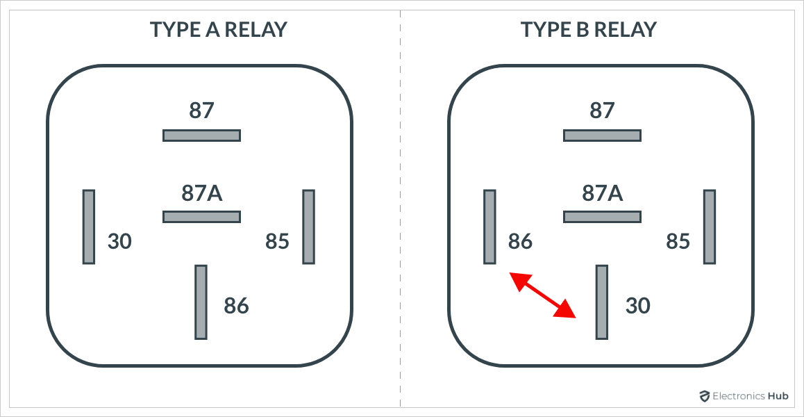
Another major classification of automotive relays is the positioning of COM pin in the relay. Depending on position of the COM relays are further classified into:
Type A Relay Type B Relay
Th above image shows the difference between Type A and Type B relays. Note that these two types are available for both 4-Pin relays as well as 5-Pin relays.
Relay Wiring Diagram
Now that we have seen the important terminology associated with relays and also the pins, let us now take a look at some commonly used relay wiring diagrams.
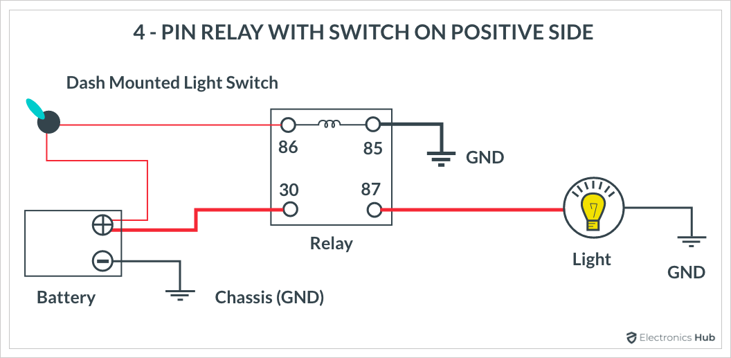
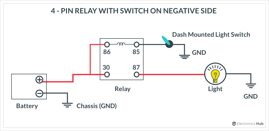
Make or Break Connection
4-Pin Relay with Switch on Positive Side
4-Pin Relay with Switch on Negative Side
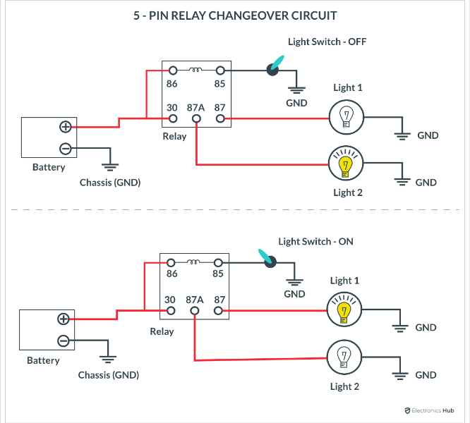
Changeover Connection
5-Pin Relay to control two different circuits.
Conclusion
Relays are very important part of many electrical system and they are an essential part of modern automotive ecosystem. They switch high power circuits with the help of isolated low power signals. Due to the mechanical nature of relays, they have wear-and-tear and we have to replace them in our cars and bikes. A knowledge of the pins of relays, relay terminology and also relay wiring diagram will be very useful if you are working with relays. Comment * Name * Email * Website
Δ




![]()