Overview
RFID or Radio Frequency Identification is a way of communication over electromagnetic wave (Radio Frequency Waves, to be specific). RFID Tags and RFID Cards are often used for authentication and access control. You might have seen people swiping their identity cards at the entrance of their offices. The identity card is in fact an RFID Card that has the personal information of the employee. The moment he/she swipes the card, his check in time will be captured by a computer.
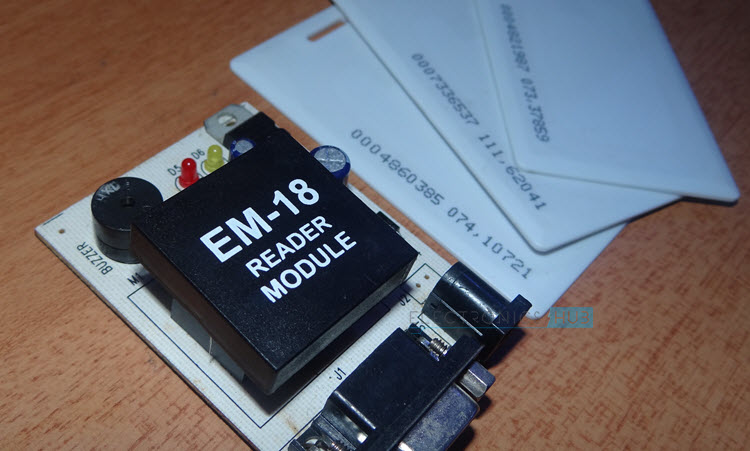
I have already implemented several projects using RFID Reader and RFID Cards like RFID Security Access Control System using 8051, RFID Based Attendance System and Arduino RFID Reader. In all those project, I have mentioned that a simple RFID Communication System comprises of three parts: an RFID Card or Tag (which contains the user or product information embedded on a chip), an RFID Reader (a device which triggers the RFID card and extracts the information from the Card) and a Host System (like a Computer or a Microcontroller which then processes the data). In this project, I will be using the popular EM-18 RFID Reader Module and a few RFID Cards. There is another popular RFID Reader called RFID RC522. The main differences between EM-18 and RC522 RFID Modules are:
EM-18 is based on 125 KHz Radio Frequency Communication while the RC522 is based on 13.56 MHz Frequency. Coming to the interface options, EM-18 uses Serial Communication whereas RC522 uses SPI Communication (although the chip supports I2C and UART as well).
So, selection of the RFID Reader Module is very important as it defines how you communicate with the module using Raspberry Pi or Arduino. I won’t go in to the details of working of the RFID Reader and RFID Communication as there are many tutorial about the same like the one here: RFID Technology and Its Applications. I will jump in to the Raspberry Pi RFID Reader Interface.
Setting up Raspberry Pi for Serial Communication
The important thing I mentioned in the Raspberry Pi RFID Reader Module Interface is the EM-18 RFID Reader Module uses UART Communication i.e. Serial Communication. If you remember, I haven’t done any projects till now that involve Raspberry Pi communicating over Serial. Before proceeding with the Interface of Raspberry Pi and RFID Reader Module, there are a few things you need to do in your Raspberry Pi in order to enable the Serial Communication in Raspberry Pi. In Raspberry Pi, the Serial Port can be used or configured in two ways: Access Console and Serial Interface. By default, the Serial Port of the Raspberry Pi is configured to access the Linux Console i.e. as Console I/O pins. But, we want to change this to act as a Serial Communication Port so that we can connected external peripherals, like RFID Reader in this project, to communicate through serial communication. In order to do this, first login to your Raspberry Pi using SSH (Putty). Enter the Raspberry Pi Configuration Tool by entering the following command. sudo raspi-config In the “Interfacing Options”, select the “Serial” option.
Now, it asks whether you would like to access the login shell over serial communication. Select “No” option. Then, it asks do you want to enable the Serial Port Hardware. Select “Yes” option.
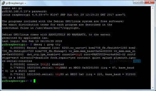
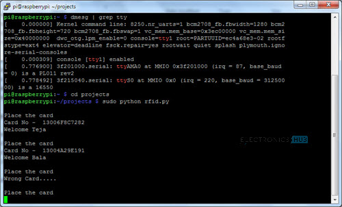
Finish the process and Reboot the Raspberry Pi. After the Raspberry Pi is powered up, once agin login using Putty and in order to check whether the Serial Port is Enabled or not, enter the following command. dmesg | grep tty
At the bottom, you can see, “ttyS0” is configured as Serial. Now, you can proceed with Interfacing RFID Reader Module with Raspberry Pi to communicate over Serial.
Circuit Diagram of Raspberry Pi RFID Reader Interface
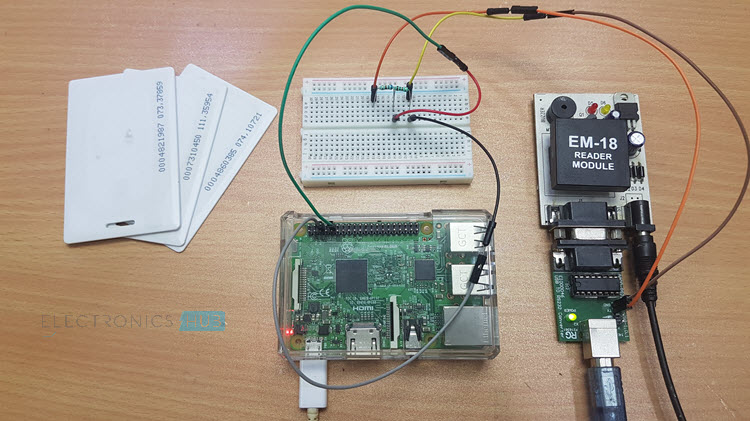
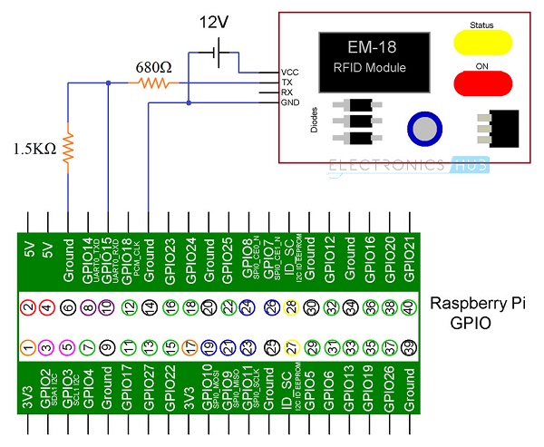
The following image shows the connections between the Raspberry Pi and the EM-18 RFID Reader.
Components Required
Raspberry Pi 3 Model B EM-18 RFID Reader Module RS232 – to – USB Adapter (as my RFID Reader has only RS232 Output) Few RFID Cards or RFID Tags Power Supply for RFID Reader (my RFID Reader has a 5V Regulator) 5V Supply for Raspberry Pi and RS232-USB Adapter Connecting Wires 680Ω Resistor (1/4 Watt) 1.5KΩ Resistor (1/4 Watt)
Circuit Design
On Raspberry Pi, the GPIO14 and GPIO14 i.e. Physical Pins 8 and 10 are the UART TX and RX Pins respectively. As we have already enabled the Serial Port of the Raspberry Pi, you can connect these pins to the external peripherals. It is now a good time to note that Raspberry Pi works on 3.3V Logic. Hence, the RX Pin of the Raspberry Pin must only be given with 3.3V Logic. In order to do that, we need to level convert the TX line of the RFID Reader to 3.3V using a simple Voltage Divider Network consisting to two resistors. I have used 680Ω and 1.5KΩ resistors. The output of the voltage divider is connected to the UART RXD pin of the Raspberry Pi i.e. GPIO15. Make a common ground connection between the Raspberry Pi and the RFID Reader Module.
Code
A simple Python Script is written to read the values from the RFID Card, compare it with the predefined values (I have already collected the data of all the RFID Cards beforehand) and display specific information.
NOTE: In the “port=’/dev/ttyS0’” line, replace ttyS0 with the name of the serial device assigned to you.
Working
The Working of the Raspberry Pi RFID Reader Module Interface is very simple. After enabling the Serial Port on the Raspberry Pi, we must assign the rest of the parameters associated with UART Communication i.e. Baud Rate, Parity, Stop Bits and the Size of the Data. All these values are set in the Python code. After this, you will get a message as “Place the Card”. When you place your RFID Card on the RFID Reader, the RFID Reader Module it will read the data from the Card and sends the data to the Raspberry Pi over Serial Communication. This data is further analyzed by the Raspberry Pi and appropriate messages are displayed in the screen.
Applications
Interfacing RFID Reader with Raspberry Pi can be very useful as you can implement a wide range of applications like:
Access Control Authentication e-Ticket e-Payment e-Toll Attendance
Comment * Name * Email * Website
Δ






![]()