When two or more waves of the same frequency are interfering in a medium or made to travel in the same path, then the “phase” of waves play an important role to produce the desired output without any noise occurring in it. Phase can also be defined as “The relative displacement of two waves with respect to each other”.
Phase can be expressed in radians and degrees also. One radian = 57.3 degrees.
Phase Difference
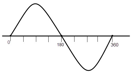
The phase difference of a sine wave can be defined as “The time interval by which a wave leads by or lags by another wave” and the phase difference is not a property of only one wave, it’s the relative property to two or more waves. This is also called as “Phase angle” or “Phase offset”. The phase difference represented by the Greek letter Phi (Φ). The complete phase of a waveform can be defined as 2π radians or 360 degrees. Leading phase means, a waveform is ahead of another wave with the same frequency and Lagging phase means, a waveform is behind another wave with the same frequency. Phase quadrature: When the phase difference between two waves is 900 (it may be = + 900 or – 900), then the waves are said to be in ‘Phase quadrature’. Phase opposition: When the phase difference between two waves is 1800 (it may be = + 1800 or – 1800), then the waves are said to be in ‘Phase opposition. To understand this concept clearly, observe the figure below.
The time interval and phase of a waveform are inversely proportional to each other. It means t deg = 1 / (360 f ) (Degrees) t rad = 1 / (6.28 f ) (Radians) Where f is the frequency of the waveform and t is the time period. For example, if two sine waves have the same frequency and have a phase shift of π/2 radians, then the phases of the waves can be defined as (nπ + 1) and nπ radians. The phase shift of the waveforms can be represented in time period (T) also. For example + 6ms and – 7ms etc. Back to top
Phase Difference Equation
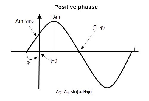
The phase difference of sine waveforms can be expressed by below given equation, using maximum voltage or amplitude of the wave forms, A(t) = Amax×sin(ωt±Ø) Where Amax is the amplitude of the measures sine wave ωt is the angular velocity (radians / Sec) Φ is the phase angle. (Radians or degrees) If Φ < 0, then the phase angle of the wave is said to be in negative phase. Similarly, if Φ > 0, then the phase angle of the wave is said to be in a positive phase.
Phase Relationship of a Sinusoidal Waveform
Every alternating waveform will have its current , voltage and frequency. If the voltage and angular velocities of the two waveforms are same, then their phase is also same at any instant of time.
In the above picture,we can see three waves which are starting at the origin of the axis, leading at origin and lagging at the origin of the coordinate axis respectively. Back to top
Phase Difference of Waveforms
Out of Phase
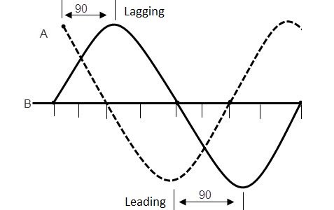
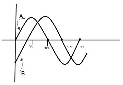
When alternating waveforms have the same frequency but different phase, they are said to be “Out of phase”. The phase difference is not zero for out of phased waves. Observe the below figure which describes the out of phase concept of two sine waves. For in phase waveforms, the retardation is fractions of numbers of wavelengths like 1/2, 2/3, 3/5… etc.
In the above picture, the wave ‘B’ leads by 900 (Φ = 900) to wave ‘A’. So we can say that the two waves are out – of – phase. For out of phased waves, there are two conditions. They are
- Leading phase
- Lagging phase When two waveforms of the same frequency are travelling along the same axis and one waveform is ahead of another, then it is called ‘Leading phase wave’. The current and voltage equations for leading phased waveforms are Voltage (Vt) = Vm sin ωt Current (it) = Im sin (ωt – Φ) Where Φ is leading phase angle. When two waveforms of the same frequency are travelling along the same axis and one waveform is behind of another, then it is called ‘Lagging phase wave’. The voltage and current equations for leading phased waveforms are Voltage (Vt) = Vm sin ωt Current (it) = Im sin (ωt + Φ) Where Φ is lagging phase angle.
IN Phase Sine Waveforms
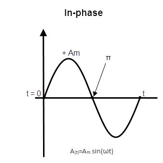
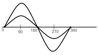
When the difference between phase of two alternating waves is zero, the waves are said to be “In-phase”. This can be occurred when the two waveforms have the same frequency and the same phase. For in phase waveforms, the retardation is a whole number of wavelengths like 0, 1, 2, 3… The in-phase waveforms are shown in below figure.
The waveforms in the above picture have different amplitude (maximum voltage) but they have the same frequency. Ex: If two sine waves A & B are out of phase and the phase difference is 250 then we can explain the relation between the waves as Wave ‘A’ leads by wave ‘B’ by 250 or wave ‘B’ lags by wave ‘A’ by 250. So the current and voltages of these waveforms also vary with the phase shift of the out of phased waveforms. Back to top
Voltage and Current Phase Relationships to R,L,C
The R L C circuit is also called as “Resonance circuit”. The voltage and current behaviour of the resistor, capacitor and inductors with respect to phase is explained below.
Resistor: In resistor, the current and the voltage are in the same phase. So the phase difference between them is measured as 0. Capacitor: In a capacitor, the current and voltages are not in the same phase and the current leads voltage by 900. So the phase difference between current and voltage in a capacitor is measured as 900. Inductor: In inductor also, the current and voltages are not in the same phase. The voltage leads current by 900.So the phase difference between voltage and current in capacitor is measured as 900. This is exactly opposite to nature of the capacitor.
NOTE:
There is a simple technique to remember this voltage, current relationship, without any confusion. That technique is C I V I L The first 3 letters C I V represents that, in a capacitor, I (current) leads V (voltage).
Back to top
Summary
We can summarize this total concept as Phase: The position of the moving particle of a waveform is called “Phase” and is measured in “Radians or degrees”. Phase difference: The time interval by which a wave leads by or lags by another wave is called “Phase difference” or “Phase angle”. It is defined by ‘Φ’. The phase angle is measured in “Radians / Sec” or “Degrees / Sec” and the phase of a complete cycle is stated as “3600”. Out of phase: When alternating waveforms have the same frequency but different phase, they are said to be “Out of phase”. In-phase: When the difference between phase of two alternating waves is zero, they are said to be “In-phase”. Leading phase: A waveform is ahead of another wave with the same frequency. Lagging phase: A waveform is behind another wave with the same frequency. In LRC circuits, the phase relationship between voltage and current will be In Resistors: The phase of voltage and current is same. So the phase difference is 0. In capacitors: Current leads voltage by 90 degrees. So the phase difference is 900. In Inductors: Voltage leads current by 90 degrees. So the phase difference is 900.
Back to top Comment * Name * Email * Website
Δ





![]()