ARM 7 based LPC2148 is one of the successful and popular 32 – bit microcontrollers. It has many on – chip features. But today, we are going to concentrate on the serial communication i.e. UART feature of the LPC2146 MCU. In this project, we are going to interface the Bluetooth module with the ARM 7 based MCU i.e. LPC2148. In the later projects, we will use this interface and develop some advanced projects. One of the major applications of Bluetooth module is in the field of Home Automation and Smart Home systems, where a Bluetooth enabled device like a smart phone or tablet can be used to control the smart home application.
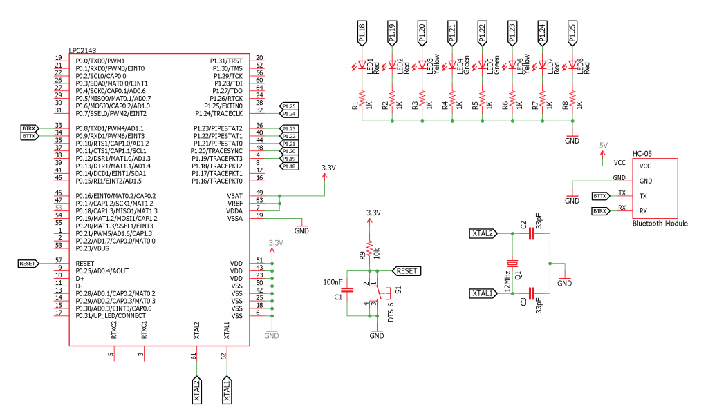
Circuit Diagram
Components Required
Since we are using the LPC2148 development board in this project, some of the mentioned components might already be embedded on to the board. The components required for the implementation of the project are as follows:
LPC2148 Microcontroller based stand – alone or complete development board HC – 05 Bluetooth Module (any UART based Bluetooth module) 8 x LEDs 8 x 1 KΩ Resistors USB – to – Mini USB Cable Power supply Connecting wires Smart Phone with “Bluetooth Controller” Application
Circuit Design
The circuit design for the interface of Bluetooth Module with LPC2148 involves the connection between the HC – 05 Bluetooth Module and the ARM7 based MCU LPC2148. The details of the complete circuit design are as follows. The HC – 05 Bluetooth module is an UART based device. Hence, the connection between the LPC2148 and Bluetooth module requires only two wires. In LPC2148, there are two UART modules: UART 0 and UART 1. The UART 0 in our development board is connected to the USB to serial converter. So, we are connecting the Bluetooth Module to the UART 1 i.e. PORT0 Pins P0.8 (Pin 33) and P0.9 (Pin 34). The TX pin of the Bluetooth Module is connected to RXD1 (P0.9 – Pin 34) of LPC2148. Similarly, the RX pin of the Bluetooth Module is connected to TXD1 (P0.8 – Pin 33) of LPC2148. Note: The TX and RX pins of Bluetooth Module can tolerate only 3.3V. Since the output of the LPC2148 MCU is only 3.3V, the connections can be made directly. The Bluetooth Module has on – board 3.3V regulator. So, 5V supply can be given to the module. In order to demonstrate a successful transmission of data between the Bluetooth Module / LPC2148 and smart phone, we are turning few LEDs ON and OFF. As the board already consists of LEDs, we are not connecting any additional LEDs. On the development board, the LEDs are connected to PORT1 Pins P1.18 to P1.25. So, we will write the program as per these pins.
Working of the Project
The project successfully demonstrates the interface of Bluetooth Module with LPC2148. It involves the UART Module of the LPC2148. So, it is advised to read our UART tutorial for LPC2148 MCU. As mentioned in the circuit design, the Bluetooth Module is connected to UART 1 module in the LPC2148. When the Bluetooth module is successfully paired with the smart phone, we can configure the application in the phone to transmit the desired data. In the program, it is configured that when “0” is received by the Bluetooth Module, all the LEDs that are connected as per the circuit diagram will be turned ON. Similarly, when “1” is received, all the LEDs will be turned OFF. So, it is important to configure the UART module properly. Also, the PLL module is used to generate CCLK and PCLK. The configuration of PLL module and other related information are explained in our ARM PLL Tutorial.
Code
Understanding the Program
The programming part of the project includes configuring the GPIO pins, PLL0 Module, UART1 Module and controlling the LEDs. We will see how these modules are configured individually. First is the PLL0 module. PLL0 module is configured to generate the system clock i.e. CCLK at 60 MHz. So, we will enable the PLL0 module and also set the multiplier and divider values. In order to do that, we will use the following commands. PLL0CON = 0x01; PLL0CFG = 0x24; Once the PLL0 module in initialized and the multiplier and divider values are set, the next step is to fix these multiplier and divider values. For this, we will use the following feed sequence. PLL0FEED = 0xAA; PLL0FEED = 0x55; Now, we will check if the PLL0 module is locked to the specified values with the help of PLL0STAT register and once it is locked, we will connect the PLL module. while (! (PLL0STAT & 0x00000400)); PLL0CON = 0x03; Another Feed sequence is written to lock the PLL0 module. Now, the CCLK will oscillate at 60 MHz. PLL0FEED = 0xAA; PLL0FEED = 0x55; Finally, the peripheral clock is configured to replicate the system clock. VPBDIV = 0x01; The next module we are going to discuss is the UART module. As mentioned earlier, we are using the UART1 module in the project. So, the first step is to select the TX1 and RX1 pins using the PINSEL register. PINSEL0 = 0x50000; We need to set the UART frame format for data transmission. With the following instruction, we will set it as 8 Data bits, no Parity bits and 1 Stop bit. U1LCR = 3 | (1«7); We need to set the Baud Rate to 9600 bps. For that, the DLL and DLM values are set as follows. U1DLL = 110; U1DLM = 1; Now, for more accurate baud rate, the Mulval and Divval values are set. U1FDR = (MULVAL«4) | DIVADDVAL; All the values are locked using the following command. Also the RX and TX FIFO is enabled for data transmission and reception. U1LCR &= 0x0F; U1FCR = 0xC1; With these commands, the UART is setup successfully and is ready to receive and transmit the data. The next step is to read the received data and turn the LEDs ON or OFF. char c = UART1Read(); if( c == ‘0’ ) { IO1SET = 0x03FC0000; } else if (c == ‘1’) { IO1CLR = 0x03FC0000; }
Applications
Interfacing a Bluetooth Module with a Microcontroller has many advantages and applications. The best example is in the area of Smart Home systems and Home Automation systems. With a powerful processor like ARM7, the range of applications can be increased to industrial, robotic and consumer grade applications.
Comment * Name * Email * Website
Δ
![]()
![]()
![]()


![]()
![]()

