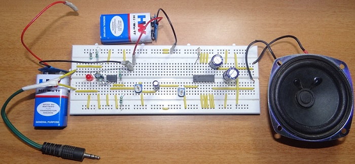
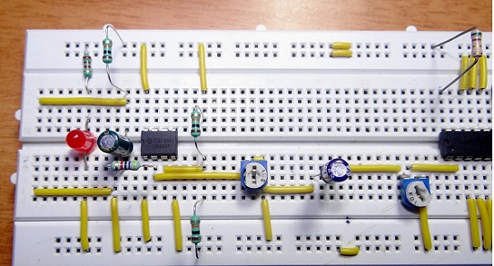
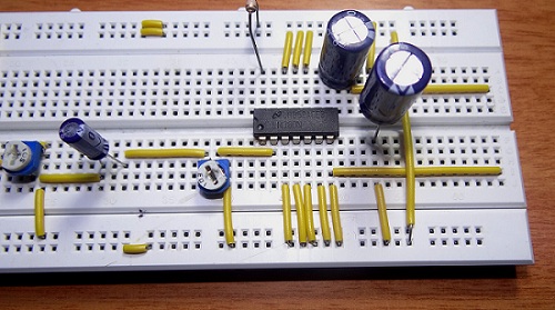
Hence, the best position of a preamplifier is close to the sensor or detector. The output of the preamplifier is further amplified by Power Amplifiers. Preamplifier amplifies the signal with very high gain but doesn’t have the drive current or current gain to drive the output. Hence, the boosted signal from preamplifier is given to a power amplifier where the current is amplified. If the input signal is subject to filtering, the filtering circuit may add noise to the signal. When a preamplifier is used, the noise can be considerably reduced. Preamplifier also helps in minimizing the noise in the lines when the sensor and power amplifier are placed at a distance. Even though power amplifiers are the circuits that drive the output, the volume control on power amplifiers is difficult. Often, the gain of power amplifier is kept more or less constant, while the volume is controlled at the preamplifier stage. There are three types of preamplifiers: current sensitive, charge sensitive and parasitic capacitance for different sensors, detectors and applications like microphone preamplifier, music recording studios, television antenna etc. In this project, a preamplifier is designed for an electret microphone with mono output. The circuit can also be used for audio from phones or other weak signal devices which normally are sufficient for headphones. As the preamplifier doesn’t have the drive capability, a simple audio amplifier is also added to the circuit.
Circuit Diagram
Components Required
LM358 – 1 LM380 – 1 10KΩ – 3 1KΩ – 1 2.2Ω – 1 1 MΩ POT – 1 10 KΩ POT – 1 470µF – 2 4.7µF – 1 0.1µF – 1
Circuit Design of Preamplifier
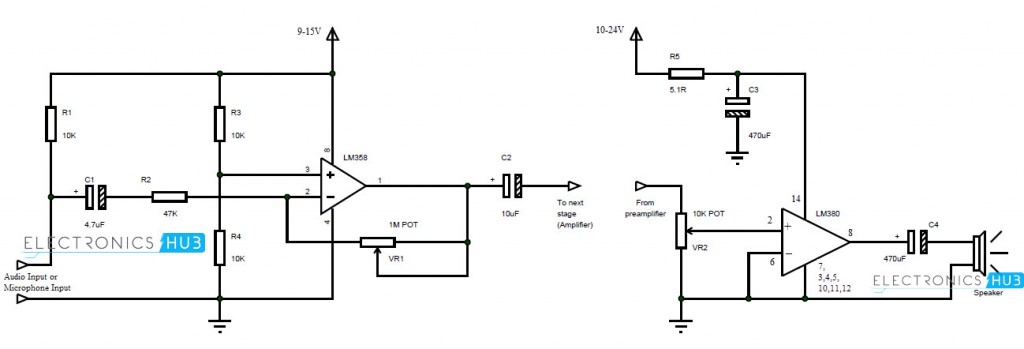
In the preamplifier circuit, LM358 Op-Amp is used. It is connected in a negative feedback fashion with a 1MΩ POT connected in the feedback path. The input from the microphone is given to the inverting terminal of the op amp while the non-inverting terminal is given with a constant input from the voltage divider formed by R3 and R4. Minimum supply voltage must be 9V and the gain of the circuit can be controlled by adjusting the POT.
Circuit Design of Amplifier
In the amplifier circuit, LM380 audio amplifier is used. The output power of the amplifier is 2.5W and the internal gain of it is fixed at 34dB. It can be used in consumer applications like TV sound systems, FM receivers, alarms, intercoms etc. In this amplifier circuit, the non-inverting terminal is given with the output of the preamplifier via 10KΩ POT while the inverting terminal is grounded. The filtered output is taken from pin 8 and is given to a speaker.
Working
A simple microphone preamplifier based on LM358 is designed in this project. In order to complete the circuit, a simple audio amplifier is also designed. The working of the circuit is as follows.
An Electret microphone or audio from phone is considered as the input. This is given to the inverting terminal of the op amp. The input to the non-inverting terminal is a constant supply from the voltage divider. This signal is amplified according to the gain set by the POT. The input signal, which is in the order of few milli volts is amplified to few volts. But the current of the signal is very less. Hence, this preamplified signal is given to the amplifier circuit formed by LM380. The output of the preamplifier is given to the non-inverting terminal of the audio amplifier. LM380 amplifies the current of the signal in order to drive an output device like a small 8Ω speaker. Proper filters are placed in the circuit to minimize distortions.
Applications
The preamplifier circuit designed here can be used to boost the signal from a microphone and make it ready to be given to a power amplifier. Audio from phones, MP3 players etc. can be given to this preamplifier before giving it to a proper amplifier. The output audio from phones isn’t sufficient to be given to small audio amplifiers like LM380 or LM386. It is necessary to implement a preamplifier stage before the actual amplification.
Note
The circuit can be used in pre-amplification of signals from electret microphones. When used in combination with an audio amplifier, like in this circuit, it is advised to adjust the volume in the preamplifier section as it doesn’t disturb the gain of the audio amplifier. In order to implement a good quality sound system, it is an advantage to use a preamplifier as it enhances the low level audio signals. Depending on the design, a preamplifier can amplify input signals that are as low as few micro volts (µV).
Few More Interesting Projects:
Wireless Transmitter and Receiver using RF Modules How To Make Automatic Battery Charger? Portable Ultrasonic Range Meter 12V DC to 220V AC Converter Circuit Variable Power Supply Circuits How To Make Portable Battery Charger? How To Make Microphone Preamplifier?
Comment * Name * Email * Website
Δ


![]()