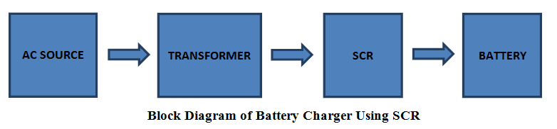
Block Diagram of Battery Charger Using SCR: The AC source is given to the step down transformer which converts the large AC source into limited AC source, filter the AC voltage and remove the noise and then give that voltage to the SCR where it will rectify the AC and give the resulting voltage to the battery for charging.
Circuit Diagram of Battery Charger Using SCR
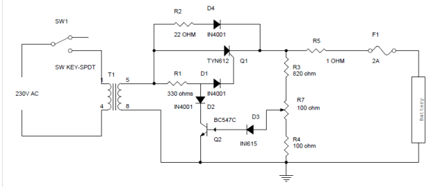
Circuit diagram of the Battery Charger Circuit using SCR can be seen below
Circuit Diagram Explanation
The AC main voltage is given to the step down transformer the voltage should be down to 20V approx. the step down voltage is given to the SCR for rectification and SCR rectifies AC main voltage. This rectified voltage is used to charge battery. When the battery connecter to the charging circuit, the battery will not be dead completely and it will get discharged this will give the forward bias voltage to the transistor through the diode D2 and resistor R7 which will get turned on. When the transistor is turned on the SCR will get off. When the battery voltage is dropped the forward bias will be decreased and transistor gets turned off. When the transistor is turned off automatically the diode D1 and resistor R3 will get the current to the gate of the SCR, this will triggers the SCR and gets conduct. SCR will rectifies the AC input voltage and give to the battery through Resistor R6. This will charge the battery when the voltage drop in the battery decreases the forward bias current also gets increased to the transistor when the battery is completely charged the Transistor Q1 will be again turned on and turned off the SCR.
Also read the post: Lead Acid Battery Charger Circuit
Battery Charger Circuit using SCR and LM 311
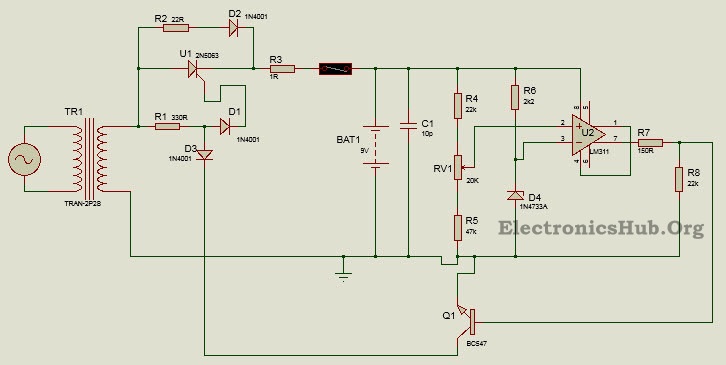
Here is another circuit controlled battery charger using an SCR and LM311 . The AC signal is rectified using a SCR and a comparator is used to detect the battery charge voltage with respect to a reference voltage so as to control the switching of the SCR.
Principle Behind this Circuit
The principle behind the circuit lies in controlling the switching of an SCR based on the charging and discharging of the battery. Here the SCR acts as a rectifier as well as a switch to allow the rectified DC voltage to be fed to charge the battery. In case the battery gets fully charged, this situation is detected using a comparator circuit and SCR is turned off. When the battery charge drops below a threshold level, the comparator output is so as to turn the SCR on and the battery gets charging again. Here the comparator compares the voltage across the battery with a reference voltage.
Circuit Diagram of Battery Charger Circuit using SCR and LM311
Circuit Design of Battery Charger using SCR and LM311:
Designing the whole circuit depends on the kind of battery used to be recharged. Suppose we are using a 6 cell, 9V Ni-Cd battery with an ampere hour rating of 20Ah and a single cell voltage of 1.5V. This would set the required optimum battery voltage to be around 9V. For a voltage of 9V across the potential divider, the voltage across the pot and resistor should be above 5.2V (reference voltage level). For this purpose we select a potential divider arrangement consisting of 22K resistor, 40K resistor and a 20k pot. Output current from LM311 is about 50mA and since here we are using transistor BC547 with a low base current, we require a resistor of about 150 ohms. The transformer used is a 230/12V transformer. Primary of the transformer is connected to 230V AC supply whereas the secondary is connected to the rectifier.
How to Operate Battery Charger Circuit?
Initially when the circuit is powered and the battery level is below the threshold voltage, the circuit performs the task of charging the battery. The SCR gets triggered with a voltage at its Gate terminal through the resistor R1 and diode D1. It then starts rectifying the AC voltage, though only for the half cycle. As the DC current starts flowing to the battery through the resistor R2, the battery gets charged. The voltage across the potential divider consisting of the pot RV1 and resistor R4 depends upon the voltage across the battery. This voltage is applied to the inverting terminal of the OPAMP LM311. The non inverting terminal is given a reference voltage of 5.2V using a Zener diode. For normal charging operation, this reference voltage is more than the voltage across the potential divider and the output of the comparator is less than the threshold voltage required to trigger the NPN transistor into conduction. The transistor and the diode D3 thus remains off and the SCR gate gets triggering voltage through R1 and D1. Now when the battery starts charging and at a certain point when it is fully charged, the voltage across the potential divider reaches a value above the reference voltage. This implies the voltage at the inverting terminal is less than the voltage at non inverting terminal and the output of the comparator is more than the threshold base emitter voltage for the transistor. This causes the transistor to conduct and it is switched on. At the same time as the diode D3 is forward biased, it starts conducting and this blocks the triggering the SCR gate voltage as it is now connected to low potential or ground. The SCR thus gets switched off and the charging operation is stopped or paused. Again when the battery charge drops below the threshold level, the charging operation resumes in the manner described above. The resistor R7 and diode D4 are to ensure a small amount of trickle charging takes place in case of the SCR being in off condition.
Applications of Battery Charger Circuit using SCR and LM311:
Thank you….
Comment * Name * Email * Website
Δ
![]()
![]()
![]()
![]()
![]()

