The control system can also be defined as “The collection or group of devices”, that regulates or manages the behavior of other systems. For example, we use control systems in heavy industries (called industrial control systems) to control the production machinery. Simply, a control system can be stated as the system which controls the other system by its output.
Various electronic components in a control system are connected physically with the aid of I/O devices like responders, sensors. By using the inputs and by processing the outputs of other blocks in the system, the output of a control system controls the physical process of a mechanical operation. The control systems can perform other operations like transforming one signal to another signal, as per the response of desired system. In a simple electronic system, we have input and outputs in the form of signals. We can represent a system in many ways, such as pictorial, descriptive, schematic and mathematical etc. Most of the electronic systems are schematically represented as a series of interconnected signals and blocks. In this, each block will have its individual inputs and outputs. Each block in a control system will represent a system or an individual component of a system. Back to top
Examples of control systems in real life
The need and usage of automation and automation devices is increasing day by day by in this modernized world. Automation means the process of controlling the devices by using another system. In practical, every aspect of human life is affected by at least one control system in day to day life. For example a refrigerator in our house, a geezer and an air conditioner etc are some sort of control systems. Mostly we use control systems in industrial purposes like quality controlling of products, power systems, robotics, space technology, weapons system and transportation system etc.
Block Diagram Representation of a Simple Electronic System
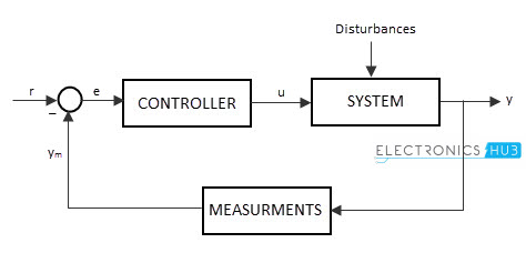
The representation of an electronic system as a number of inter-connected boxes or blocks is called as “Block Diagram Representation of a system”. The block diagram of a basic electronic system is shown below.
As we stated earlier, every control system will certainly have inputs and out puts. The outputs are produced by processing the inputs. So the input signals connected to a block of the system will change the system’s behavior. We can decide a system operation and its functioning by analyzing its input and output. This process is generally known as “Cause and Effect analysis”. Let’s see to an audio system in our home. It is a control system designed by combining multiple system blocks like micro phone, amplifier and sound speaker. Its micro phone acts as input device which converts the sound signals into electrical signals. These signals are amplified by using amplifier. The amplified output is fed as input to the loud speaker, which produces the sound waves. This is a basic type of control system where there is no complexity. There are some complex control systems with many feedback controls and many sub systems. Such as connecting this simple audio system to the multi input systems like DVD player, MP3 player or a CD player. An electronic system should not only contain input and outputs, it must “do something”. In case of the electrical switch and sensors and bulbs.If they are connected together, the sensor device will act as input device and it detects the light and sends that information to the electronic switch, as current signals or voltage signals. When these signals are received by output device i.e. actuator, then it converts the processed signal into mechanical movement. Back to top
Types of electronic system
Any electronic system will operate depending on its input signal. These input signals may be Continuous time or discrete time.
Continuous system
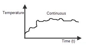
The system, in which the input signals are defined along the analog signal which is continuity in nature, is called “Continuous system”. The continuous system will vary its magnitude with time period T.
Recording or measuring a room temperature is a continuous time signal. The temperature is measured between two required, the values may be days (like, between Monday to Saturday) or temperature levels (like, from cold to hot) etc. So we will represent the continuous system by continuous time signal and the continuous time signal is described by using the variable t. Many of the signals we come across, like current signal, voltage signal, velocity, pressure and temperature signal etc are continuous signals.
Discrete system
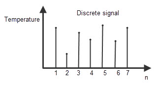
The system, in which the input signals are sequence of discrete time values, is called “Discrete system”. These discrete values are defined or obtained at the particular interval of times. The output of discrete systems is represented as s sequence of numbers.The discrete values specified are of equally spaced intervals or equally spaced points of time. Let’s discuss about the same temperature measurement process which we explained in continuous system. Here we will measure the temperature at specific intervals like 1pm, at 2pm, at 3pm and again at 4pm etc. Representing continuous system as a set of discrete intervals We can represent a continuous signal X (t) in the form of discrete signal, at discrete intervals of time. By sampling the time period of continuous signal n intervals, we can represent the continuous input signal as x (n) and continuous output signal as y (n).Back to top
Features of Control System
To be a good control system, a system must have a clear mathematical equation between input and output. If the input and outputs of a system are in linear proportionality relation, the system is known as “Linear control system”. If the input and outputs of a system are in non – linear proportionality relation, the system is known as “Non linear control system”.
Requirement of Good Control System
There are some specifications for a system to be a good control system. They are listed below.
Sensitivity
The parameters of a control system depends upon its surroundings. They always change when there is change in surroundings. The rate of change of a control system with the change in its surroundings is called “Sensitivity”. A good control system should be sensitive to its input only and should not be sensitive to the surrounding parameters.
Accuracy
The tolerance to errors of an instrument is known as “Accuracy”. It defines the limits of errors of an instrument at normal operating conditions. We can improve the accuracy by using feedback elements. We should provide the error detector circuit in the control system to increase the accuracy.
Stability
This is the key characteristic that will decide the nature of a control system. Stability of a system can be explained as, if the input of the system is zero or null then its output should also be zero value. If the input changes, the output also changed as per the system function. Then the system is considered as “stable”.
Noise
The undesired signal input that is occurred or added to input signal by external resources is known as “Noise”. A good control system should have the high noise tolerance value. This means it should be able to reduce the noise level. If the noise occurrence increases, the system performance will decrease.
Speed
In a control system, the time taken by the output to be stable is known as “Speed”. High speed systems are considered as good control systems. The time taken by the output to reach its stable state is known as “Transient state”.
Bandwidth
Bandwidth is defined as the range of frequencies of a system. Band width is decided by the operating frequencies. The system having high band width is considered as a good control system.
Oscillation
Oscillation means the fluctuations of output of system. These oscillations will effect the stability. The increase in the number of fluctuations of a system will decrease the stability of the system. Back to top
Types of control systems
We use many different types of control systems to control the velocity, temperature, pressure, voltage and current of different systems. Based on their working, control systems are classified as 2 types. They are
Manually control system
The system which is controlled only by the user instructions is called as “Manually controlled systems”. For example, consider an Air Conditioner, which is used to control the room temperature. When the electric switch connected to the A.C. is on, and then it runs and controls the room temperature. Previously, we set a temperature value to control the operation of the A.C. when the system (here in this example, system refers to A.C.) reaches the pre-setted temperature, then it stops working that means it will tend to be in idle state. If we want to make the system to function again, we will change the pre-set temperature levels, manually. So these types of systems are called manual control systems.
Automatic control system
The above air conditioning system is further improvised by connecting a timer circuit to it. We can set the timer to such intervals to make the system ON and OFF. When the system reaches the pre-set temperature and it again to be started controlling the temperature after some time period. This time interval is set in the timer device. So when the system requirements reach the preset conditions, the system will turn ON automatically. Such types of systems are called “Automatic control systems”. Back to top
Feedback concept
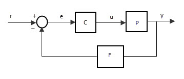
Feedback means “Connecting some part of output to its input”. The feedback concept is most common technique to achieve stability of control system. The connection made from output to input is called as “Feedback loop”. The feedback loop enables the system to adjust with the system parameters and surrounded parameters to attain the desired output response. The importance of feedback is that sometimes we can provide changes to the system by varying or changing the values or components such as sensors, attenuators, amplifiers etc to get the desired output. But in many cases, such as industrial control systems, it is not possible to open the entire system and make changes to them. So we use the feedback loop, which is already calculated and set to the accurate level and connected to the input, to get the desired output. The example for the control system with feedback loop is shown in the above diagram, in which the
Block C represents the controller Block P represents the process and Block F represents the feedback path
Back to top
Classification based on feedback loop
Depending upon feedback loop nature of the control system, the controls systems are classified as 2 main types. They are
- Positive feedback system
- Negative feedback system
Positive feedback system
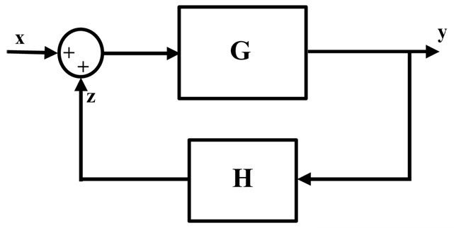
The system with positive feedback loop connected to its input is called “Positive feedback system”.
Negative feedback system
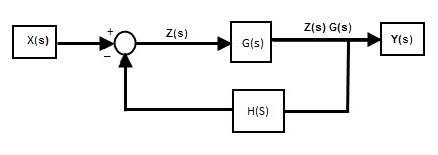
The system with negative feedback loop connected to its input is called “Negative feedback system”. Depending upon feedback loop connection type of the control system, the controls systems are classified as 2 main types. They are
- open loop control system
- Closed loop control system
Open loop control system
A control system in which the control action is totally independent of output of the system then it is called “open loop control system”.
Closed loop control system
Control system in which the output has an effect on the input quantity in such a manner that the input quantity will adjust itself based on the output generated is called “closed loop control system”.
Back to top Comment * Name * Email * Website
Δ






![]()