In this project, I will show you how to build a 2 digit up down counter circuit using both 8051 Microcontroller and ATmega8 Microcontroller.
2 Digit Up Down Counter Circuit Principle
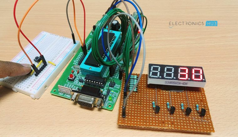
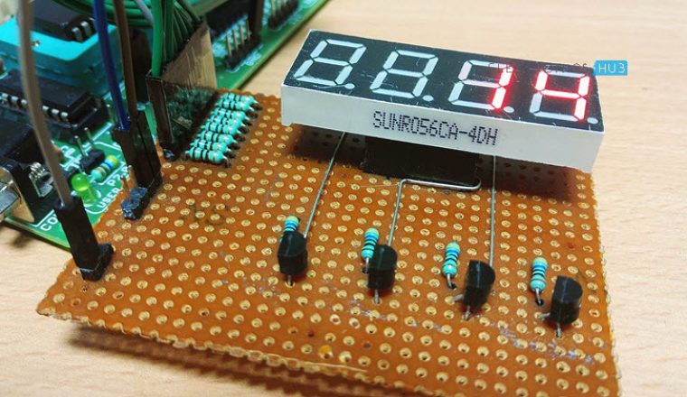
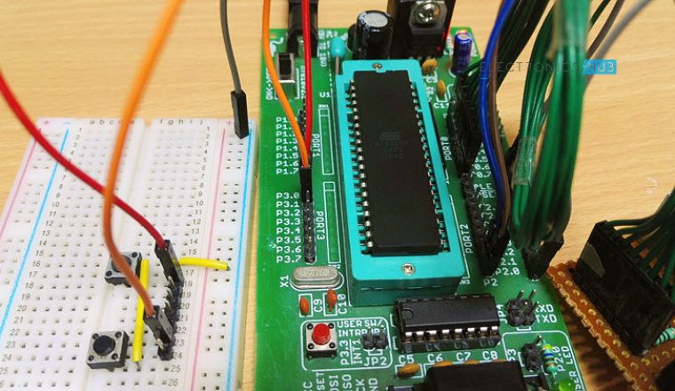
Main principle of the 2 Digit Up Down Counter circuit is to increment the values on seven segment displays by pressing the button. When button 1 is pressed, the value on the display is incremented by one and when the other button is pressed, the value on the display is decremented by one. The value on the display can be incremented and decremented from 0-99 as it uses only 2 displays. If you want to display 3 digits, three displays should be used i.e. three 7-Segment Displays. There are many circuits available for 2 digit up/down counter but using a microcontroller reduces components and space on the board but simple programming is required.
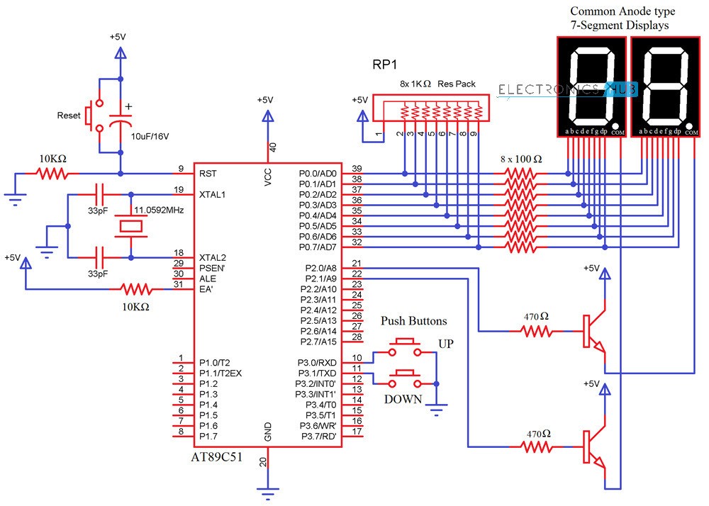
Two Digit Up Down Counter Circuit Diagram
Circuit 1: Using 8051 Microcontroller
Components Required
AT89C51 (8051 Microcontroller) 2 X 7-Segment Displays (Common Anode) 2 X 2N2222 NPN Transistors 3 X Push Buttons 2 X 10KΩ Resistors 2 X 470Ω Resistors 8 X 100Ω Resistors 11.0592 MHz Crystal 2 X 33pF Capacitor 10μF/16V Capacitor 1KΩ X 8 Resistor Pack Mini Breadboard 5V Power Supply 8051 Programmer
Circuit 2: Using ATmega8 Microcontroller
Components Required
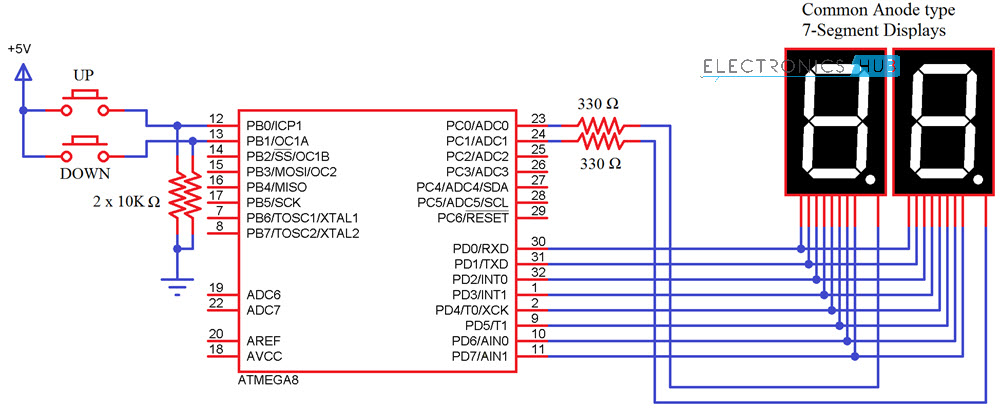
ATmega8 Microcontroller 2 X 7-Segment Displays (Common Anode) 2 X 10KΩ Resistors 2 X 330Ω Resistors 2 X Push Buttons
Circuit Design of 2 Digit 7-Segment Up Down Counter
The 2digit Up/Down counter consists of two seven segment displays connected to ATMEGA8 microcontroller. The seven segment display consists of 8 pins and one common pin. There are mainly two types of seven segment displays 1) common cathode 2) common anode. The display here used is common cathode display. Generally for common cathode displays, common pin should be grounded and for common anode, it should be connected to VCC. In Seven segment display, there are seven segments and they are similar to seven LEDs. Seven pins belong to these seven segments where as the last pin is dot at the coner of the display. For common cathode, display assigning logic1 to the segment pin glows particular segment. In case of common anode, the segment pin should be assigned logic0 in order to glow the segment. Each segment is given one name starting from ‘a ‘and last segment dot is ‘h’. In our circuit, seven segment display is connected to micro controller through a current limiting resistor of 330 ohms. Two buttons in pull- down mode are also connected. The necessity of connecting the buttons in pull down mode is to avoid floating state of the button i.e. unknown state. If the button is connected in pull down mode, this ensures that button is initially in logic0 state.
Two Digit Up Down Counter – Circuit Simulation Video
How to Operate 2 Digit Up Down Counter Circuit?
Algorithm for Programming
dp g f e d c b a 1 1 1 1 1 0 0 1 This is because b and c segments should be assigned with logic 0 to display ‘1’, I am using a Common Anode 7-Segment Display . So, the binary value 0b11111001 or the hexadecimal value 0xf9 is assigned to the particular port on which ‘1’ is to be displayed. The array should consist of 0-9 binary or hexa values.
CODE
Code for 8051 Microcontroller
Code for ATmega8 Microcontroller
2 Digit Up Down Counter Circuit using ATmega8 Output
2 Digit Up Down Counter Circuit Applications
Limitations of this Circuit
This particular Up/Down Counter circuit is limited to 2 digits i.e. 0-99. If more than 3 digits are required, one should use another display which requires more pins from the controller. Thank you very much Best regards THANK U could really use your help. thank you. best regards -Thanks Would the code work if I use an Atmega16-8ML. Also, how would I go about if I use 4 displays? Comment * Name * Email * Website
Δ




![]()